Category Archives: Uncategorized

PVI Holdings, Inc. acquired by MiddleGround Capital

PVI Holdings, Inc. acquired by MiddleGround Capital

FOR IMMEDIATE RELEASE

PVI Holdings, Inc. acquired by MiddleGround Capital

Baton Rouge, LA (July 19, 2022) – MiddleGround Capital has acquired PVI Holdings, Inc. MiddleGround is an operationally-focused private equity firm that makes control investments in the North American middle market primarily focused on B2B industrial and specialty distribution companies.

Included in this transaction are Setpoint Integrated Solutions Inc., W&O Supply, Inc. and A-T Controls, Inc.

“It was a cultural fit from our first meeting, MiddleGround brings a unique style to private equity that has my team fired up about the future.” said Brad Bergeron, PVI CEO. “We value their operational expertise, passion for continuous improvement, and believe they are the perfect owner for PVI’s next phase of growth.

“We are extremely excited to partner with MiddleGround on the next step of our journey.” said Matt Bate, Setpoint President. “Setpoint’s focus on caring for and creating value for our people, our customers and the communities we serve will continue. Our partnership with MiddleGround will enhance and accelerate those efforts and create additional opportunities for growth.”


About Setpoint Integrated Solutions (and its subsidiaries)

Setpoint is the leader in the process control industry with nearly 700 dedicated employees supporting 12 facilities across the Gulf Coast. Setpoint’s portfolio includes industry-leading new and remanufactured valve and instrumentation lines serving multiple market segments along with best-in-class repair services.

For more information, please visit www.setpointis.com.


About MiddleGround Capital

MiddleGround Capital is a private equity firm based in Lexington, KY with over $2.4 billion of assets under management. MiddleGround makes control equity investments in middle market B2B industrial and specialty distribution businesses. MiddleGround works with its portfolio companies to create value through a hands-on operational approach and partners with its management teams to support long-term growth strategies.

For more information, please visit: www.middlegroundcapital.com.


CONTACT:

Ben Davis, Vice President of Sales

346-954-4900

bdavis@setpointis.com

Setpoint Integrated Solutions Announces Matt Bate as new President & CEO

Setpoint Integrated Solutions Announces Matt Bate as new President & CEO

Media Contact:
Fatima Mehr, Director of Marketing
FMehr@setpointis.com
225.235.5687

Baton Rouge, LA (May 11, 2021) – Setpoint Integrated Solutions is pleased to announce that effective May 31, 2021, Matthew Bate, current Setpoint Chief Financial Officer, will be promoted to the role of President & Chief Executive Officer. Bate will succeed Jeff Birch, who will transition to Managing Director, President & Chief Executive Officer of fellow Pon Holdings organization, The Hiller Companies.

“The continuous improvement culture that we’ve created within Setpoint is fast-paced, consistently evolving, and embraces positive change,” Birch said. “As I reflect on the last few years of growth and success at Setpoint, I am incredibly proud of the many accomplishments of the organization and have the utmost confidence in Bate’s ability to lead the outstanding people and business of Setpoint.”


Bate is a graduate of Texas A&M, receiving both his Bachelor of Business Administration and Master of Science in Finance from the Mays School of Business. Prior to joining Setpoint as the Chief Financial Officer in 2018, Bate held various leadership roles at PWC,  Schlumberger, and Pon. Bate and his wife, Hayley, have two young children, Austin and Reese.


“On behalf of Setpoint, I want to thank Jeff for his leadership over the past 5 years.  Setpoint is extremely well  positioned for continued growth with strong OEM partnerships and established customer relationships, but most importantly, exceptional people throughout our organization.  We will continue to operate within our core operational priorities led by our total commitment to safety and quality and manage our business through data-driven analytics and digital investment,” Bate said. “Together with Setpoint’s leadership team and more than 700 employees, I’m confident we will continue to perform at the highest level for our customers.”

About Setpoint Integrated Solutions

Setpoint Integrated Solutions is the leader in the process control industry with 11 facilities across the Gulf Coast. Supporting the Power, Refining, and Chemical Industries with best in class valve repair services, delivering process solutions for control, relief, and automated valve requirements, along with industrial equipment including liquid level measurement, pressure gauges, and more.  Setpoint Integrated Solutions, headquartered in Baton Rouge, La., is a subsidiary of Pon Holdings B.V. of the Netherlands. Pon is an international trading and service organization with a workforce of 14,000 people spread over 450 locations in 32 countries.


For more information, please visit www.setpointis.com and www.pon.com/en


PDF Found Here

Setpoint Integrated Solutions Continues to Expand Territory Agreement with Ashcroft Inc.

Setpoint Integrated Solutions Continues to Expand Territory Agreement with Ashcroft Inc.

Media Contact:
Fatima Mehr, Director of Marketing
FMehr@setpointis.com
225.235.5687

Baton Rouge, LA (July 31, 2020) – Setpoint Integrated Solutions (Setpoint I.S.) and Ashcroft Inc. will continue to build on their established partnership by expanding the existing Authorized Stocking Distributor agreement to include three new Texas locations for the sale of Ashcroft Inc.’s line of Pressure and Temperature Instruments.

“Ashcroft Inc. continues to be a valuable partner as we expand our valuable partner as we expand our distribution and seal assembly capabilities,” said Jeff Kelley, Vice President of Sales at Setpoint I.S. “This expansion allows Setpoint I.S. to further our vision of growth in the Texas market as well as build on our product portfolio, adding to the plant level service offerings across the Gulf Coast.”

Setpoint I.S.’ existing territory in the region includes the Texas “Golden Triangle” and East Texas. The expansion includes three new Setpoint I.S. Texas locations: La Porte, Richwood and Corpus Christi. These distributing facilities service the Houston, San Antonio, Austin and Corpus Christi areas for the sale of the Ashcroft Inc. Pressure and Temperature Instruments.

Setpoint I.S. and Ashcroft Inc.’s partnership dates back over 60 years, and Setpoint I.S. continues to be the legacy representative in the East Texas, Louisiana, Mississippi, Alabama and Florida panhandle territories. The expanded territory will capitalize on the successful track record of serving end user needs within the refining, petrochemical and power industries.

Products manufactured by Ashcroft Inc. have become the benchmark in pressure and temperature measurement and include gauges, thermometers, switches, transducers, transmitters, instrument isolators and diaphragm seals as well as control and calibration equipment.

For additional details, contact Stuart Prestridge, Corporate Director of Sales at SPrestridge@setpointis.com or 225.921.9846.

About Setpoint Integrated Solutions

Setpoint Integrated Solutions is the leader in the process control industry with 11 facilities across the Gulf Coast. Supporting the Power, Refining, and Chemical Industries with best in class valve repair services, delivering process solutions for control, relief, and automated valve requirements, along with industrial equipment including liquid level measurement, pressure gauges, and more.  Setpoint Integrated Solutions, headquartered in Baton Rouge, La., is a subsidiary of Pon Holdings B.V. of the Netherlands. Pon is an international trading and service organization with a workforce of 14,000 people spread over 450 locations in 32 countries. 


For more information, please visit www.setpointis.com and www.pon.com/en


About Ashcroft
Ashcroft was founded over 165 years ago with a mission to protect our customers with a brand recognized for reliability and innovation in the fields of pressure and temperature measurement. Ashcroft maintains operations in the United States, Mexico, Brazil, Germany, China and Singapore along with over 235 channel partners in 55 countries supporting our customers around the world. Ashcroft is headquartered in Stratford, CT, USA and is a subsidiary of Nagano Keiki Co., Ltd. based in Tokyo, Japan. 


PDF Found Here

Clark Reliance Territory Expansion

Setpoint Integrated Solutions Expands Territory Agreement with Clark-Reliance

FOR IMMEDIATE RELEASE


Setpoint Integrated Solutions expands territory agreement with Clark-Reliance.


Baton Rouge, LA (Dec. 4, 2018) – Setpoint Integrated Solutions (Setpoint I.S.) is pleased to announce that effective midnight Dec. 1, 2018 Setpoint I.S. will expand the exclusive Representative contract into Texas for following brands:

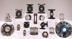
  • Jacoby-Tarbox® sight flow indicators, security sight windows, lighting products, eductors (jet pumps) and tank liquid agitators.
  • Jerguson® Gage & Valve reflex & transparent glass level gages, valves, and illuminators.
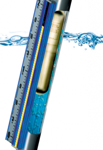
  • Jerguson® Magnicator Products magnetic level gages, switches, and transmitters.
  • Jerguson® (Magne-Sonics®) Level Switches external caged and top mount float & displacer switches
  • Reliance® boiler water level gages including: reflex, transparent mica protected, bicolor glass and conductivity probe remote type, valves and illuminators.


Setpoint I.S. and the Clark-Reliance Corporation’s partnership dates back to 2000, and Setpoint I.S. continues to be the legacy representative in North TX, Louisiana, Arkansas, and Southwest Mississippi Territories. The expanded territory will capitalize on the successful track record of serving end user needs within the refining, petrochemical, and power industries.


“Our goal from day one has been to align with “Best in Class” manufacturers who engineer products focused on improving the safety, reliability, and run time efficiency of our end users. Clark-Reliance has been a great partner for many years, and the expansion further into Texas will enhance our continued growth within Setpoint’s Instrumentation & Distributed Product Portfolio. ” said Jeff Kelley, Vice President of Sales and Marketing for Setpoint Integrated Solutions.  “To support the local customers, we have invested in additional inventory and personnel to maximize our ability to provide a rapid response, quick shipments, and technical support throughout the process,” Kelley continued.


For additional details, contact Stuart Prestridge, Director of Business Development at SPrestridge@setpointis.com or 225.921.9846.  RFQ’s can be directed to ClarkRelianceRFQ@setpointis.com and will be handled promptly.   


About Clark Reliance Corporation

Founded in 1884, Clark-Reliance is dedicated to supplying the largest and broadest product line in the instrumentation industry for all types of measurement and control. Key acquisitions over the last few decades have solidified Clark-Reliance as a leader in the separation and filtration industries as well.


Clark-Reliance now includes a number of distinguished product lines: Reliance®, Jerguson®, Jacoby-Tarbox®, Anderson® Separator and National Filtration Systems®


About Setpoint Integrated Solutions

Setpoint Integrated Solutions is the leader in the process control industry with 12 facilities across the Gulf Coast. Supporting the Power, Refining, and Chemical Industries with best in class valve repair services, delivering process solutions for control, relief, and automated valve requirements, along with industrial equipment including liquid level measurement, pressure gauges, PLC’s and more. Setpoint Integrated Solutions, headquartered in Baton Rouge, La., is a subsidiary of Pon Holdings B.V. of the Netherlands. Pon is an international trading and service organization with a workforce of 14,000 people spread over 450 locations in 32 countries. For more information, please visit www.setpointis.com and www.pon.com/en .


PDF found here.

Replace Your Globe Valves with the Camflex GR from Masoneilan

Replace Your Globe Valves with the Camflex GR from Masoneilan

Fast Facts about the Masoneilan Camflex :

  • First introduced in 1968 the Masoneilan Camflex Rotary Globe control valve has over 1.2 Million units installed worldwide
  • Setpoint Integrated Solutions has over 40,000 Camflex Rotary Globe control valves installed across the Gulf Coast coverage area
  • Per API 553 recommended practices for Refinery valves, Camflex Rotary Globe valve is recommended in refinery distillation, FCCU, catalytic reformer, delayed coker, gas plant,, and sulfur recovery unit.
  • Camflex Rotary Globe has performed for decades in difficult applications  including brine water, dry chlorine, HCL,  Heater Drain, Saturated Steam, Ammonia, Vinyl Chloride, Vinyl Acetate, Titanium Tetrachloride, Sulfuric Acid, Sulfur, Steam Condensate, Rich Amine, Bottom Residuals, Phosphorus Trichloride, Phosphorous acid, Alumina silica acid, Nitric Acid, Dowtherm, Green and Black Liquor.
  • Camflex Rotary Globe combined with the SVI II AP SMART positioner exhibits high-resolution throttling control performance achieving .002 inch step change (2 thousands of an inch), 0% overshoot, 1.5 sec. settling time, step change time .01 sec., wait time 10 sec.
  • Higher fluid recovery factor offering more resistance to cavitation than a segmented ball control valve
  • Multiple inherent flow characteristics are available including linear, =% 30, =% 50 and customized characterized characterization when combined with SVI II AP SMARt positioner
  • Slurry service design available with o-ring sealed bearings, hardened flow gallery, protected outlet, and ceramic trim options
  • Camflex Rotary Globe offers two face to face take out lengths, ISA S75.04 Segmented Ball Valve, and ISA S75.03 Globe Valve


The Camflex Rotary Globe valve offers several advantages over reciprocating control valves
  • Standard low emission packing in compliance with ISO-15848 & ANSI/FCI 91-1
  • 50% fewer parts, 50% fewer potential leak paths, 50% lighter than a typical reciprocating globe control valve
  • Higher turndown, 100:1 turndown as compared to reciprocating globe valve with 50:1
  • Multiple CV’s available for optimum control range where only a seat ring change-ou is required
  • Unique seating design offers standard ANSI/FCI 70-2 leakage class IV & V with metal to metal sealing components
  • Standard extended bonnet allows the use of low friction TFE packing over the full operating range

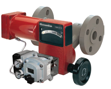
Baker Hughes’ Masoneilan Camflex GR

Baker Hughes’ Masonielan Camflex valve technology has over 1.2 Million units installed worldwide in refineries, petrochemical, and chemical plants. The original Camflex design, since being introduced in 1968, has been proven to be reliable where many typical valves fail. And now, the new Camflex GR (Globe Replacement) model makes operation and maintenance even easier.

Available in six sizes, 1″/ 1.5″/ 2″/ 3″/ 4″ / 6″ in carbon or stainless steel constructions.  Models rated for three classes 150 / 300 / 600 applications

With 50% fewer parts, the Camflex GR has simpler operation, easier maintenance, and lower inventory costs for spares.   It also features 50% fewer potential leak paths for higher efficiency and lower emissions.  It is lightweight, easy to handle, and simple to commission.

The Camflex GR is designed for direct, 1-to-1 replacement of most reciprocating valves. Its compact envelop makes it easy to install in any application, regardless of which OEM made your old valve.

Camflex GR’s rotary design has several advantages over  the typical reciprocating globe valves that it replaces. At the heart of the Camflex is the double eccentric plug design.  Eccentric rotating, self-aligning plug results in reliable shutoff and fewer leaks.

The eccentric action ensures no friction or contact between the plug and seat during operation. The only time the plug contacts the seat ring is when the valve closes.  This ensures consistent and tight shut off. Additionally, the  Camflex GR has 2x the Cv of conventional globe valves which provides exceptional turn-down, or rangeablility,  to cover many process conditions.

The rotary shaft motion reduces packing friction and wear, providing tighter longterm sealing. No sliding stem results in less friction, simpler packing.  The standard EF Seal provides low emission tightness.  The integral body design eliminates the typical gasketed body, or bonnet joint, simplifying maintenance and removing a potential leak point. Fewer gasketed joins results in less chance for environmental issues.  Direct mounting of positioners provides more accurate positioning control by eliminating intermediate linkage between the valve shaft and avoiding lost motion that could otherwise be caused by wear over time.

Most importantly,  unlike traditional globe valves,  the Camflex trim is designed  so that only the seat ring changes for different Cv requirements. Combined with a simpler design with less packing and no gaskets, this means few parts to stock and manage., resulting in huge cost savings.

Camflex GR is available from Setpoint Integrated Solutions through the ValvFast program, meaning kits are in-stock and can be configured to meet your application needs in as little as 24-hours.

Properly Protect Against Overpressure

Properly Protect Against Overpressure

Properly Protect Against Overpressure

Understand the appropriate use of different pressure relief devices.

By Amin Almasi, rotating equipment consultant

Many processes require a device to control or limit the pressure that can build up due to an upset , instru­ment or equipment failure, or fire. Pressure relief valves (PRV) most commonly provide this protection against overpressure but backflow preventers (such as check valves and others) and rupture disks also play useful roles in many applications. In addition, special classes of relief valves, usually known as vacuum relief valves, safeguard against excessive vacuum. Such devices actuate when pressure (or vacuum) exceeds a specified design value.

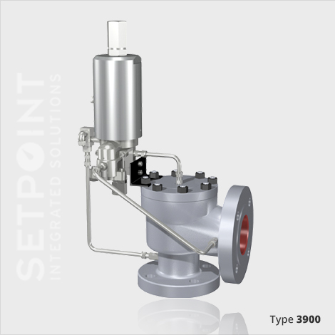
A conventional PRV is a self-actuated spring-loaded valve that opens at a designated pressure to allow the pressurized fluid to exit. (Some small valves commonly handle thermal relief valve applications.) The basic ele­ments of a spring-loaded PRV include an inlet nozzle connected to the vessel or system to be protected, a movable disk that regulates flow through the nozzle, and a spring that controls the position of the disk.

Under normal system operating conditions, the pressure at the inlet is below the set pressure – so, the disk is seated on the nozzle, preventing flow through it.

However, when the set pressure is exceeded, the relief valve opens and becomes the “path of least resis­ tance” for flow. A portion of the fluid exits the PRV, usually going through a piping system known as a flare header or relief header to a central, elevated gas flare (or similar) for combustion. The loss of fluid lowers the pressure inside the machinery or system being pro­ tected. When the pressure declines enough, the PRV will close. How much the pressure must drop before the valve reseats is termed blow-down and often is stated as a percentage of set pressure. Roughly, this can range from 3% to 20%; some valves have adjustable blow-downs.

PRESSURE RELIEF VALVE
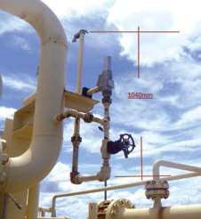
Figure 1. When open, this valve vents fluid to atmosphere.

In systems where the outlet is connected to piping, the PRV’s opening will prompt a pressure build  up in the downstream piping. Other PRVs connected to the outlet pipe system may open and the pressure in

the exhaust pipe system may increase . This may cause undesired operation. So, such systems frequently need an alternative solution. They often require “differen­tial” relief valves –  in these, the pressure works on an area much smaller than the opening area of the valve.

The pressure must decrease enormously before the valve closes; also the outlet pressure of the valve can easily keep the valve open.

In some cases, a bypass valve protects a pump or gas compressor and any associated equipment from excessive pressure . It acts as a relief valve by returning

all or part of the fluid discharged by the pump or com­ pressor back to either a storage reservoir or the inlet of the machine. The bypass valve and bypass path can be internal (an integral  part of the  pump or compressor) or external (installed as a component in the fluid path) .

CONVENTIONAL SPRING-LOADED PAV

The operation of this device is based on a force bal­ance. The spring load is preset to equal the force exerted on the closed disk by the inlet fluid when the system pressure is at the PRV’s set pressure. When the inlet pressure is below the set pressure, as it should be for normal operations, the disk remains seated on the nozzle in the closed position. As the system pressure approaches the set pressure of the valve, the seating force between the disk and the nozzle approaches zero.

When the inlet pressure exceeds set pressure, the pressure force on the disk overcomes the spring force and the valve opens. Then when the inlet pressure falls to the closing pressure, the valve recloses.

Historically, many liquid applications used PRVs (or pressure safety valves) designed for compressible (or vapor) service. Many of these valves when used in liquid service required high overpressure (say, 20%) to achieve full lift and stable operation because liq­ uids don’t provide the expansive forces that vapors do. Where liquid PRVs had to operate with a 10%

overpressure limit, a conservative factor (say, 0.6) usu­ ally was applied to the valve capacity during sizing.

Consequently, many installations were oversized and instability sometimes resulted.

Codes now incorporate rules that address perfor­ mance ofliquid service valves at 10% overpressure and that require a capacity certification. Vendors have

developed PRVs for liquid services that achieve full lift, stable operation and rated capacity at 10% over­ pressure in compliance with the requirements; some designs feature adjustable blow-down. Valves that can operate on liquid and gas are available. However, such valves may exhibit different operational characteristics depending upon whether the flow stream is liquid, gas or a combination of the two. Many PRVs designed for liquid service, for example, will have a much longer blow-down (typically 20%) on gas than on liquid ser­ vice. Additionally, some variation in set pressure may occur if the valve is set on liquid and required to oper­ ate on gas or vice versa.

Pressure existing at the outlet of a PRV  is defined as backpressure. This backpressure may cause varia­ tions in opening pressure, reduction in flow capacity, instability or a combination of all three. A balanced spring-loaded PRV minimizes the effects ofbackpres­ sure on the performance characteristics of the valve; it incorporates a bellows, a sealed piston or other means of balancing the valve disk. Consider a balanced PRV wherever the backpressure  created by flow through the downstream piping after the relief valve lifts is too high for a conventional PRV. Balanced PRVs also can

serve to isolate the guide, spring, bonnet and other top works parts within the valve from the relieving fluid. This may be important if corrosive damage to these parts from the fluids (such as dirty ones from down­ stream) is a concern.

Two-phase systems in which the fluid being relieved may be liquid or gas call for spring-loaded PRVs designed for liquid (or liquid-and-gas) service and bal­ anced to minimize the effects ofbackpressure. Many manufacturers recommend use of valves designed for liquid or liquid-and-gas service if the mass percent­ age of vapor in the two-phase  mixture at the valve inlet is 50% or less. If you’re not certain of the ratio of liquid to gas in the flow stream, selecting a valve spe­ cifically designed for liquid or liquid-and-gas service is prudent.

Conventional PRVs perform unsatisfactorily when excessive backpressure develops during a relief inci­ dent, due to the flow through the valve and outlet piping. The built-up backpressure opposes the lifting force that’s holding the valve open . Excessive built-up backpressure can make the valve operate in an unsta­ ble manner. This instability may occur as chatter or flutter. Chatter refers to an abnormally rapid recipro­ cating motion of the valve disk where it contacts the seat during cycling. This type of operation may cause damage to the valve and interconnecting piping. Flut­ ter is similar to chatter except the disk doesn’t contact the seat during cycling.

As a rough guide, in a conventional PRV applica­ tion, built-up backpressure shouldn’t  exceed 10% of the set pressure at 10% allowable overpressure. You may use a higher maximum built-up backpressure for allowable overpressures greater than 10% –  provided the built-up backpressure doesn’t surpass the allowable overpressure. When the superimposed backpressure is constant, you can reduce the spring load to compensate for the superimposed backpressure. When the back­ pressure is expected to exceed these specified limits, specify a balanced or pilot-operated PRV.


PILOT-OPERATED PAV

This device consists of the main relief valve, which normally encloses a floating unbalanced piston assembly, and an external pilot (usually a conventional PRV).

The piston is designed to have a larger area on the top than on the bottom. Up to the set pressure, the top and bottom areas are exposed to the same inlet operating pressure. Because of the larger area on the

top of the piston, the net force holds the piston tightly against the main valve nozzle. As the operating pres­ sure increases, the net seating force rises and tends

to make the valve tighter . This feature allows most pilot-operated valves to be used where the maximum expected operating pressure is higher than the percent­ age acceptable for conventional relief valves. At the

set pressure, the pilot vents the pressure from  the  top of the piston; the resulting net force is now upward, causing the piston to lift and thus permitting fluid flow through the main valve. After the overpressure inci­ dent, the pilot will close the vent from the top of the piston, thereby reestablishing pressure; the net force will cause the piston to reseat.

The main valve of the pilot-operated PRV can use a diaphragm system in place of a piston to provide the unbalanced moving component. A disk, which

normally closes the main valve inlet, is integral with a flexible diaphragm. The external pilot serves the same function to sense fluid pressure, vent the top of the diaphragm at set pressure, and reload the diaphragm once the fluid pressure is reduced. As with the piston valve, the seating force increases proportionally with the operating pressure because of the differential exposed area of the diaphragm. Built-up backpressure doesn’t affect the lift of the main valve piston or dia­ phragm. This allows for higher pressures in the relief discharge manifolds than prudent with conventional and balanced spring-loaded PRVs.

The modulating pilot can handle gas, liquid or two­ phase flow applications. In contrast to a pop-action PRV, a modulating pilot-operated valve limits the amount of relieving fluid to just the amount necessary to prevent the pressure from exceeding the allowable level. Because a modulating pilot only releases the required relieving rate, you can calculate the built-up backpressure based on that rate instead of the rated

relieving capacity of the valve. The modulating pilot valve also can reduce interaction with other pressure control equipment in the system during an upset con­ dition, decrease unwanted atmospheric emissions, and lower the noise level associated with discharge to the flare piping or atmosphere .


BACKFLOW  PREVENTER

You need a backflow preventer when there’s a possi­ bility of developing a pressure on the discharge side of the valve that exceeds its inlet pressure. The higher discharge pressure can create sufficient upward force on the diaphragm, piston or other element to open the valve and cause flow reversal. Reverse flow can occur with any standard type or design of pilot-operated PRV when sufficient reverse differential pressure exists.

A backflow preventer permits the introduction of outlet pressure into the dome of the main valve, thereby holding the piston firmly on the nozzle and overcoming the effect of a reverse differential pressure. The backflow preventer allows the discharge pressure to provide a net downward force on the diaphragm or piston to keep the valve closed. Proper operation of the backflow preventer is critical to further ensuring no flow reversal occurs in the valve. The material and seals in the backflow preventer should match those of the pilot-operated PRV.

RUPTURE DISKS

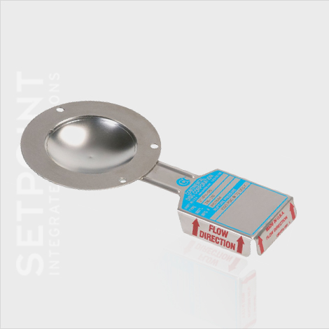
These are non-reclosing devices for protecting against excessive pressure (or sometimes vacuum). A single or multiple rupture disks may be used in an instal­ lation. They also can serve as redundant pressure relief devices.

With no moving parts, rupture disks are simple and reliable –     and faster acting than other pressure relief devices. Rupture disks react quickly enough to relieve some types of pressure spikes. Because of their light weight, rupture disks can be made from high-alloy and other corrosion-resistant materials that aren ‘t practical for relief valves.

A rupture disk is also a temperature-sensitive device. Burst pressures can vary significantly with its temperature, which may differ from the normal fluid operating temperature . As the temperature at the disk increases, the burst pressure usually decreases. Because the effect of temperature depends upon the rupture disk design and material, consult the manu­facturer for specific applications. Specify the pressure and temperature at which the disk is expected to burst.

SIZING AND RELIEF PRESSURE

Carefully evaluate the contingencies that can cause overpressure in terms of the pressures generated and the rates at which fluids must be relieved. You need the package’s process and instrumentation drawings, equipment specification sheets, and design basis for the facility to calculate the individual relieving rates for each pressure relief device. An important parameter is the set pressure of a PRV installed in the machinery, package or facility. As a rough guide, this set pressure could be 110% of the maximum allowable working pressure (MAWP) in the package or system protected by a single pressure relief device sized for operating (non-fire) contingencies .

A multiple-device installation requires the combined capacity of two or more pressure relief devices to alle­viate a given overpressure contingency. In this way, you might increase the set pressure, for instance , to 118% of the MAWP in a package protected by multi­ple pressure relief devices sized for operating (non-fire) contingencies . For fire cases, the relief pressure (set pressure) usually is higher – e.g., it could be around 120% or 125% of the MAWP in a package protected by devices sized for fire contingencies.

OVERPRESSURE CAUSES

An unbalance or disruption of the normal flows of fluid and energy in a machinery system or package can prompt the energy or fluid, or both, to build up in some part of the package (such as its discharge). Analysis of the causes and magnitudes of this over­ pressure, therefore, is a special and complex study of energy and fluid balances in different machinery oper­ating scenarios.

Double-jeopardy scenarios usually aren’t credi­ble ones for sizing a PRV. Such scenarios generally involve two independent failures or malfunctions at  the same time – e.g., simultaneous failures of two completely independent machines or controls, or oper­ator error leading to a blocked outlet coincident with an overall plant power failure. On  the  other hand, treat instrument-air failure during fire exposure as a single jeopardy if the fire exposure causes local air­ line failures.

Excessive speed and other machinery malfunctions can result in overpressure. Sometimes, the  inad­vertent opening of a valve from a source of higher pressure, such as a high-pressure  process fluid, can lead to overpressure. For instance, in many packages the re’s always a possibility of the suction system becoming pressurized by the discharge (high-pres­sure) fluid; in many cases, some portion of the suction system actually is designed based on discharge pres­sure or other means of protection (such as a PRV is considered.

A single check valve isn’t always an effective means for preventing overpressure by reverse flow from a high-pressure source such as a high-pressure discharge. For example, if a fluid is pumped or compressed into a system that contains fluid at significantly higher pres­ sure th an the design rating of the equipment upstream (suction) of the pump or compressor, loss of pumped flow with leakage or latent failure of a check valve in the discharge line results in a reversal of the fluid’s flow. When high-pressure fluid enters the low-pres­ sure system, overpressure can result . In most cases, you should focus on prevention of reverse flow. It’s important to note that , in addition to overpressure of the upstream system (or suction system), reverse flow through machinery might destroy mechanical equip­ ment, causing loss of containment. In many cases, this hazard is of concern , so provide additional means of backflow prevention.

Even proper inspection and maintenance might not completely eliminate check-valve seat leakage and leakage will occur. Consequently, even without total failure of the check valve, the low-pressure system upstream of a check valve still could be over-pressurized. A detailed analysis and study on a case-by-case basis then can show whether automatic isolation, a pressure-relief device sized for leakage, or an alternative means of protection is needed. You must define the appropriate leakage rate for each

specific machinery system. Experience has shown that when inspected and maintained to ensure reliability and capability to limit reverse flow, two back-flow­ prevention devices in series suffice to eliminate significant reverse flow.

In addition, carefully evaluate the possibility of overpressure developing from the loss of any utility service (such as cooling water, electricity, etc.), whether plant-wide or local.

AMIN ALMASI is a rotating equipment consultant based in Sydney, Australia. This post originally appeared in Chemical Processing Special Report: Review Your Rupture Disc Regimen found here. 

Review Your Rupture Disc Regimen

HPX

SPECIAL REPORT: REVIEW YOUR RUPTURE DISC REGIMEN PART 1

SPECIAL REPORT: REVIEW YOUR RUPTURE DISC REGIMEN PART 1

Standardize Rupture Disc Installations

Evaluating a plant’s pressure relief devices and updating to newer technology can lead to improved efficiency, performance and mechanical integrity.

By Richard Neale, Continental Disc Corporation  original document found here*

Many processing plants currently operating orig­inated in the 1920’s and have evolved by adding new units or lines as demand for new products increased and the technology to manufacture  those products was developed. As a result, many of these plants have a wide variety of rupture discs based on the prevailing disc technology at the time each plant addition or modification was completed.

Pressure relieving devices remain products that are individually analyzed and specified for each installation in processing plants. As pressure safety relief products, they are critical components that are the final level of protection from catastrophic failure of a pressure vessel or piping system.

When specifying rupture discs, two functions must be satisfied. The first is properly sizing and specifying the rupture disc to relieve all overpressure scenarios in a safe manner. Secondly, rupture discs must be speci­fied carefully to ensure an acceptable service life as the process operates normally.

Functioning as the sacrificial element in a pressurized system, rupture discs are considered delicate instru­ments yet must be capable of withstanding corrosive media, pressure and temperature fluctuations, pressure to vacuum cycles and other operating conditions that may impact the mechanical integrity of the rupture disc.

Recent rupture disc designs improve performance in all functions. New technology focuses on high per­formance reverse acting rupture discs that provide a means of improving flow characteristics and accuracy in overpressure relieving events in addition to improv­ing durability under normal operating conditions.

Durability is particularly important in  plants  that are extending turnaround frequency, putting greater demand on the rupture discs to withstand pressure/vacuum cycles or corrosive media for longer periods of time without compromising reliability.

Most chemical processing plants have processing units originally designed and built prior to the avail­ability of current reverse acting disc designs thus have a combination of older technology tension type rup­ture discs and reverse acting discs in newer processing plants.

Design Evolution

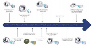
Figure 1. Rupture disc designs have evolved greatly in the past 80 years to satisfy increasing regulatory, environmental and industry demands.

As illustrated in Figure 1, rupture disc designs have evolved greatly in the past 80 years to satisfy the greater demands of OSHA for improved safety devices, the EPA to minimize potential fugitive emis­sions, and the needs of process industries to improve efficiency and mechanical integrity. This evolution pro­cess includes products with less flow restriction , that are designed to provide tighter tolerances, are available in a wider variety of materials and comply with cur­rent process safety, environmental and quality system codes, standards and directives.

With the growing emphasis on plant health and safety and protection of the environment, higher per­formance capabilities and improved durability inherent in the latest high-performance scored reverse acting disc designs make them well-suited for new construction or plant upgrades.

WHY STANDARDIZE NOW?

New high-performance scored reverse acting discs are extremely versatile in the way they can be configured to provide the optimum level of performance and  economy to each rupture disc application. In nearly all installations, reverse acting discs can replace older disc designs with significant improvement in flow capacity, accuracy and resistance to operating conditions that challenge the mechanical integrity of the rupture disc.

This greater versatility within one design of rupture disc offers greater opportunity to standardize the type of rupture disc used throughout all units within a plant site.

The standardization and optimization process can be beneficial in many ways

  • Elimination of inventory items due to standardizing similar rupture
  • Higher volume of one specification drives down
  • Greater utilization of newer rupture disc technology improves performance and
  • Familiarity with the standard product improves installation and maintenance
  • Reorganizing and upgrading inventory control is an integral part of the
  • Provides an opportunity to update compliance with industry codes; health , safety and envi­ronmental standards and company directives to current revisions

Plant sites with more than 100 rupture disc applications are going to have multiple discs in

½- through 12-in. sizes in a variety of types and materials of constru ction . Frequently, the size and material of construction remain as originally specified . Other criteria such as: the disc type, nominal burst pressure and temperature rating, manufacturing range , maximum operating pressure capability, ability to withstand vacuum or backpressure, ability to relieve liquid as well as vapor overpressure conditions can all be standardized

RUPTURE DISC

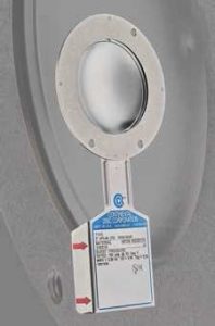
Figure 2. Modern rupture disc technology supports a range of applica­tion requirements and offers improved performance and a higher level of mechanical integrity.

WHAT IS THE PROCESS?

Analyzing the current state to determine if significant benefits can be gained from standardization is the first step. The benefits must justify the management of change process, or engineering analysis, and paper trail revisions required when upgrading or otherwise modi­fying process safety systems.

Storeroom inventory audits and plant audits, or walk-arounds, are two common services available. Plant audits provide details required to accurately determine what improvements are needed to resolve deficiencies in performance or compliance issues.

Storeroom inventory lists and audits reveal the degree to which standardization to later technology rupture discs may be possible while eliminating obsolete or duplicate items without compromising safety or performance if done properly. In a single product type, later technology reverse acting rupture discs (Figure 2) provide the versatility to support a range of application requirements and will have improved performance characteristics and a higher level of mechanical integrity compared to existing discs.

Prior to making any changes in the type of rupture disc, it is prudent to verify the type of disc proposed as a replacement for the application. This step includes a physical plant audit as well as a review of the instru­ment data sheet (IDS).

A physical plant audit of all installations can reveal several important criteria needed to complete the consolidation and upgrade analysis. The most useful criteria to record include:

Vent system configuration. Does the rupture disc vent to atmosphere or into a containment system? In some instances, the vent piping will not accommodate a rup­ture disc assembly of a different height without having to cut and reweld piping . This issue usually can be avoided by verifying and duplicating the height of the existing rupture disc assembly.

Accessibility to the rupture disc location. Hard to reach locations or installations with limited space to properly torque the mating flange fasteners benefit by using pre­-torque rupture disc holders to assure adequate force is applied to the rupture disc to provide a good seal and prevent disc slippage. This would also apply to installa­tions having flanges that are non-metallic or are lined with glass or a fluoropolymer.

Rupture discs installed at the inlet of a pressure relief valve. For these installations there are ASME code requirements that must be satisfied. All installations must have a tell-tale indicator between the two relief devices, this is frequently included as a rupture disc holder accessory. Extended height holders may be used to prevent the disc petal from extending into the valve nozzle; this eliminates the need for a spool piece that would add to the difficulty in meeting the 3% pressure loss rule.

Maximal allowable working pressure (MAWP) and temperature (MA WT) of the pressure vessel or equipment. When verifying  the MAWP and MAWT, include the type and class flange the rupture disc assembly will mate with and determine an equipment description or equipment number to ensure each disc is identified and tagged for use on the appropriate pressure vessel.

With the storeroom inventory data, IDSs, and audit findings of the current equipment, an analysis can be completed to determine the level of standardiza­ tion possible.

Recent evaluations resulted in additional ways to improve reliability, efficiency and lower maintenance costs, such as:

  • Eliminate obsolete designs such as reverse acting discs with knife blades or those that may pass unacceptable fragments of metal or graphite into downstream systems or equipment
  • Install solid metal rupture discs that are easier to seal and less sensitive to piping stress or installa­tion
  • Use noble materials such as Monel, Inconel, Hastel­loy C or Tantalum in place of less reliable coatings or linings for corrosion prevention.
  • Remove inventory that is no longer required due to specification changes or removal or replacement of the host pressure vessel or equipment.
  • Add automated alarm and control functions in criti­cal applications such as those in lethal service gasses, environmentally sensitive media or high value or regulated process media requiring a controlled and contained environment.

MOVING FORWARD

Following a full analysis of existing conditions, the ideal method of consolidating or upgrading rupture discs varies by plant type and preference but typically aligns new product installation with planned turn­ arounds or as existing inventory of rupture discs is nearly depleted.

Most processing plants have significant improvement potential. With a well-executed analysis; a well-doc­ umented justification and commitment to support the changes required; eliminating inefficiency, improvingperformance and mechanical  integrity  can all be real­ized in one standardization and optimization process.

RICHARD NEALE is the Senior Technical Analyst at Continental Disc Corporation  in Liberty, Missouri.  He can be reached at rneale@contdisc.com. Neale has been with Continental Disc for 34 years, in a variety of roles. He has experience in global markets including oil and gas, chemical, pharmaceutical, food and beverage, pulp and paper, mining and specialty gasses.

Setpoint Integrated Solutions is proud to partner with Continental Disc Corporation to meet all the rupture disc specifications you need for your application.

*This article first appeared as a Chemical Process Special Report.

Setpoint Integrated Solutions Holds Grand Opening of New Luling Facility

Setpoint Integrated Solutions Holds Grand Opening of New Luling Facility

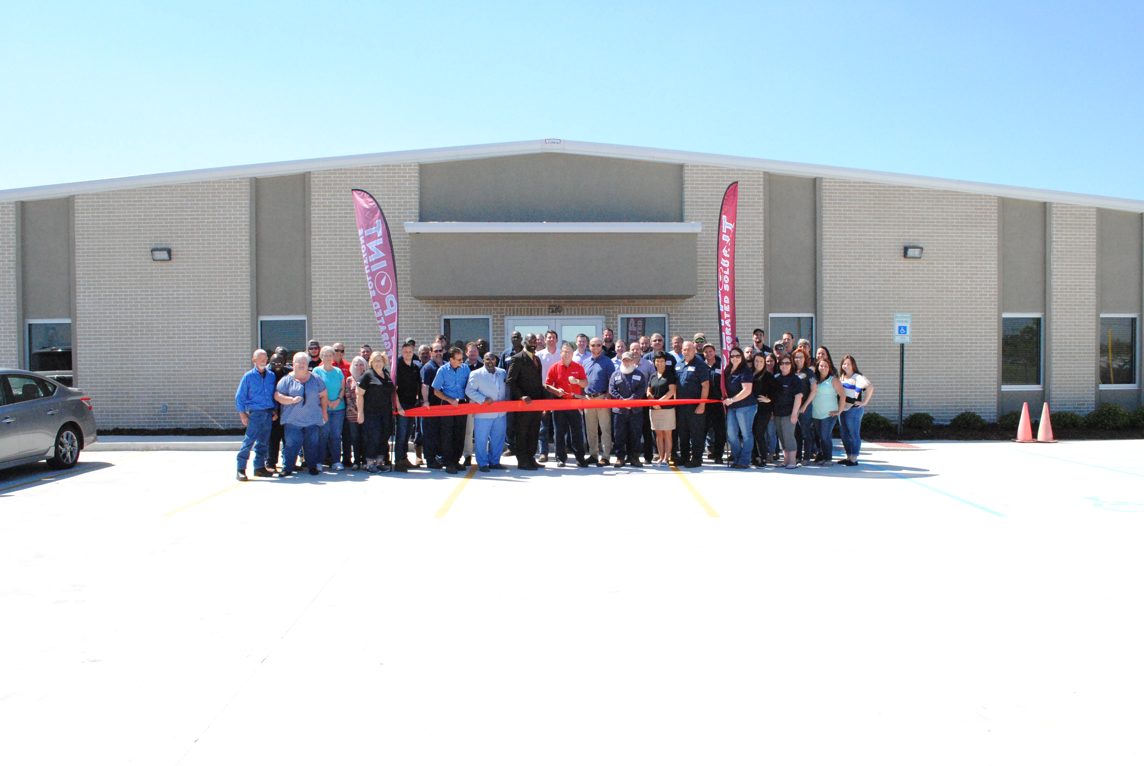
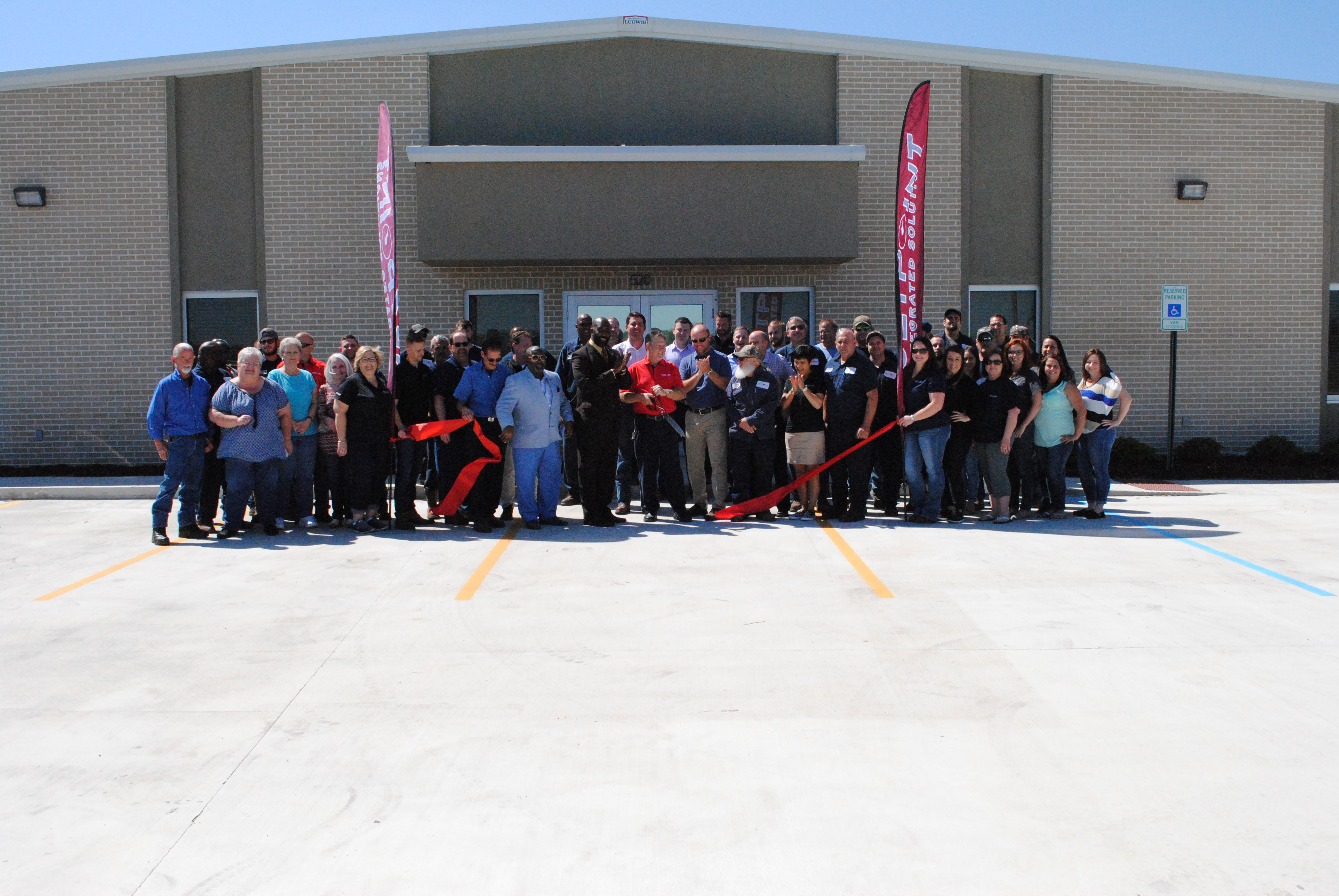
Setpoint Integrated Solutions hosted its Grand Opening for its new Luling facility on April 26th. Hundreds of customers as well as OEM partners attended for a crawfish boil, music, and door prizes.

To kick off the Grand Opening, the Chief Administrative Officer of St. Charles Parish, Billy Raymond, performed a ribbon cutting ceremony with the Setpoint I.S. team.

The new facility highlights the Setpoint Integratred Solutions commitment to the area by ensuring we are always satisfying our customers  with our Passion to Perform.

Setpoint Integrated Solutions Named Premier Distribution Partner of Gestra USA for the Gulf South Region

Logo of Gestra USA

Setpoint Integrated Solutions Named Premier Distribution Partner of Gestra USA for the Gulf South Region

FOR IMMEDIATE RELEASE

Baton Rouge, LA (March 29, 2018) – Setpoint Integrated Solutions (Setpoint I.S.) is very pleased to announce our agreement as the new, premier distribution partner of Gestra USA for Texas, Arkansas, western Tennessee, Mississippi, Alabama, Louisiana, and the Florida panhandle effective immediately.

“This agreement augments our existing offering for Steam and Condensate Management Solutions throughout our entire footprint within the Gulf South, from Texas to the Florida Panhandle up to Tennessee and Arkansas. Gestra is a premier brand and we look forward to continued partnership and growth,” said Jeff Kelley, Vice President of Sales for Setpoint Integrated Solutions.

About Gestra USA

Established in 1902 and still manufacturing in Bremen, Germany, Gestra has been physically present in the United States since 1976. Gestra is a global leader in the design and production of high quality steam traps, boiler controls, check valves, control systems and critical service valves for the efficient use and control of steam and process fluids. Gestra products have many practical uses and are applied where energy savings are desired wherever steam is generated, distributed or used, liquid & gaseous media flow, and where operational reliability and environmental protection play an important role.

About Setpoint Integrated Solutions

Setpoint Integrated Solutions is the leader in the process control industry with 13 facilities across the Gulf Coast. Supporting the Power, Refining, and Chemical Industries with best in class valve repair services, delivering process solutions for control, relief, and automated valve requirements, along with industrial equipment including liquid level measurement, pressure gauges, PLC’s and more. Setpoint Integrated Solutions, headquartered in Baton Rouge, La., is a subsidiary of Pon Holdings B.V. of the Netherlands. Pon is an international trading and service organization with a workforce of 14,000 people spread over 450 locations in 32 countries. For more information, please visit www.setpointis.com and www.pon.com/en .

PDF found here.

CONTACT:

Wyatt Link, Marketing Specialist Setpoint Integrated Solutions

Phone: (225)-612-1167

wlink@SetpointIS.com