Properly Protect Against Overpressure
Properly Protect Against Overpressure
Understand the appropriate use of different pressure relief devices.
By Amin Almasi, rotating equipment consultant
Many processes require a device to control or limit the pressure that can build up due to an upset , instrument or equipment failure, or fire. Pressure relief valves (PRV) most commonly provide this protection against overpressure but backflow preventers (such as check valves and others) and rupture disks also play useful roles in many applications. In addition, special classes of relief valves, usually known as vacuum relief valves, safeguard against excessive vacuum. Such devices actuate when pressure (or vacuum) exceeds a specified design value.
A conventional PRV is a self-actuated spring-loaded valve that opens at a designated pressure to allow the pressurized fluid to exit. (Some small valves commonly handle thermal relief valve applications.) The basic elements of a spring-loaded PRV include an inlet nozzle connected to the vessel or system to be protected, a movable disk that regulates flow through the nozzle, and a spring that controls the position of the disk.
Under normal system operating conditions, the pressure at the inlet is below the set pressure – so, the disk is seated on the nozzle, preventing flow through it.
However, when the set pressure is exceeded, the relief valve opens and becomes the “path of least resis tance” for flow. A portion of the fluid exits the PRV, usually going through a piping system known as a flare header or relief header to a central, elevated gas flare (or similar) for combustion. The loss of fluid lowers the pressure inside the machinery or system being pro tected. When the pressure declines enough, the PRV will close. How much the pressure must drop before the valve reseats is termed blow-down and often is stated as a percentage of set pressure. Roughly, this can range from 3% to 20%; some valves have adjustable blow-downs.
PRESSURE RELIEF VALVE
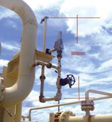
Figure 1. When open, this valve vents fluid to atmosphere.
In systems where the outlet is connected to piping, the PRV’s opening will prompt a pressure build up in the downstream piping. Other PRVs connected to the outlet pipe system may open and the pressure in
the exhaust pipe system may increase . This may cause undesired operation. So, such systems frequently need an alternative solution. They often require “differential” relief valves – in these, the pressure works on an area much smaller than the opening area of the valve.
The pressure must decrease enormously before the valve closes; also the outlet pressure of the valve can easily keep the valve open.
In some cases, a bypass valve protects a pump or gas compressor and any associated equipment from excessive pressure . It acts as a relief valve by returning
all or part of the fluid discharged by the pump or com pressor back to either a storage reservoir or the inlet of the machine. The bypass valve and bypass path can be internal (an integral part of the pump or compressor) or external (installed as a component in the fluid path) .
CONVENTIONAL SPRING-LOADED PAV
The operation of this device is based on a force balance. The spring load is preset to equal the force exerted on the closed disk by the inlet fluid when the system pressure is at the PRV’s set pressure. When the inlet pressure is below the set pressure, as it should be for normal operations, the disk remains seated on the nozzle in the closed position. As the system pressure approaches the set pressure of the valve, the seating force between the disk and the nozzle approaches zero.
When the inlet pressure exceeds set pressure, the pressure force on the disk overcomes the spring force and the valve opens. Then when the inlet pressure falls to the closing pressure, the valve recloses.
Historically, many liquid applications used PRVs (or pressure safety valves) designed for compressible (or vapor) service. Many of these valves when used in liquid service required high overpressure (say, 20%) to achieve full lift and stable operation because liq uids don’t provide the expansive forces that vapors do. Where liquid PRVs had to operate with a 10%
overpressure limit, a conservative factor (say, 0.6) usu ally was applied to the valve capacity during sizing.
Consequently, many installations were oversized and instability sometimes resulted.
Codes now incorporate rules that address perfor mance ofliquid service valves at 10% overpressure and that require a capacity certification. Vendors have
developed PRVs for liquid services that achieve full lift, stable operation and rated capacity at 10% over pressure in compliance with the requirements; some designs feature adjustable blow-down. Valves that can operate on liquid and gas are available. However, such valves may exhibit different operational characteristics depending upon whether the flow stream is liquid, gas or a combination of the two. Many PRVs designed for liquid service, for example, will have a much longer blow-down (typically 20%) on gas than on liquid ser vice. Additionally, some variation in set pressure may occur if the valve is set on liquid and required to oper ate on gas or vice versa.
Pressure existing at the outlet of a PRV is defined as backpressure. This backpressure may cause varia tions in opening pressure, reduction in flow capacity, instability or a combination of all three. A balanced spring-loaded PRV minimizes the effects ofbackpres sure on the performance characteristics of the valve; it incorporates a bellows, a sealed piston or other means of balancing the valve disk. Consider a balanced PRV wherever the backpressure created by flow through the downstream piping after the relief valve lifts is too high for a conventional PRV. Balanced PRVs also can
serve to isolate the guide, spring, bonnet and other top works parts within the valve from the relieving fluid. This may be important if corrosive damage to these parts from the fluids (such as dirty ones from down stream) is a concern.
Two-phase systems in which the fluid being relieved may be liquid or gas call for spring-loaded PRVs designed for liquid (or liquid-and-gas) service and bal anced to minimize the effects ofbackpressure. Many manufacturers recommend use of valves designed for liquid or liquid-and-gas service if the mass percent age of vapor in the two-phase mixture at the valve inlet is 50% or less. If you’re not certain of the ratio of liquid to gas in the flow stream, selecting a valve spe cifically designed for liquid or liquid-and-gas service is prudent.
Conventional PRVs perform unsatisfactorily when excessive backpressure develops during a relief inci dent, due to the flow through the valve and outlet piping. The built-up backpressure opposes the lifting force that’s holding the valve open . Excessive built-up backpressure can make the valve operate in an unsta ble manner. This instability may occur as chatter or flutter. Chatter refers to an abnormally rapid recipro cating motion of the valve disk where it contacts the seat during cycling. This type of operation may cause damage to the valve and interconnecting piping. Flut ter is similar to chatter except the disk doesn’t contact the seat during cycling.
As a rough guide, in a conventional PRV applica tion, built-up backpressure shouldn’t exceed 10% of the set pressure at 10% allowable overpressure. You may use a higher maximum built-up backpressure for allowable overpressures greater than 10% – provided the built-up backpressure doesn’t surpass the allowable overpressure. When the superimposed backpressure is constant, you can reduce the spring load to compensate for the superimposed backpressure. When the back pressure is expected to exceed these specified limits, specify a balanced or pilot-operated PRV.
PILOT-OPERATED PAV
This device consists of the main relief valve, which normally encloses a floating unbalanced piston assembly, and an external pilot (usually a conventional PRV).
The piston is designed to have a larger area on the top than on the bottom. Up to the set pressure, the top and bottom areas are exposed to the same inlet operating pressure. Because of the larger area on the
top of the piston, the net force holds the piston tightly against the main valve nozzle. As the operating pres sure increases, the net seating force rises and tends
to make the valve tighter . This feature allows most pilot-operated valves to be used where the maximum expected operating pressure is higher than the percent age acceptable for conventional relief valves. At the
set pressure, the pilot vents the pressure from the top of the piston; the resulting net force is now upward, causing the piston to lift and thus permitting fluid flow through the main valve. After the overpressure inci dent, the pilot will close the vent from the top of the piston, thereby reestablishing pressure; the net force will cause the piston to reseat.
The main valve of the pilot-operated PRV can use a diaphragm system in place of a piston to provide the unbalanced moving component. A disk, which
normally closes the main valve inlet, is integral with a flexible diaphragm. The external pilot serves the same function to sense fluid pressure, vent the top of the diaphragm at set pressure, and reload the diaphragm once the fluid pressure is reduced. As with the piston valve, the seating force increases proportionally with the operating pressure because of the differential exposed area of the diaphragm. Built-up backpressure doesn’t affect the lift of the main valve piston or dia phragm. This allows for higher pressures in the relief discharge manifolds than prudent with conventional and balanced spring-loaded PRVs.
The modulating pilot can handle gas, liquid or two phase flow applications. In contrast to a pop-action PRV, a modulating pilot-operated valve limits the amount of relieving fluid to just the amount necessary to prevent the pressure from exceeding the allowable level. Because a modulating pilot only releases the required relieving rate, you can calculate the built-up backpressure based on that rate instead of the rated
relieving capacity of the valve. The modulating pilot valve also can reduce interaction with other pressure control equipment in the system during an upset con dition, decrease unwanted atmospheric emissions, and lower the noise level associated with discharge to the flare piping or atmosphere .
BACKFLOW PREVENTER
You need a backflow preventer when there’s a possi bility of developing a pressure on the discharge side of the valve that exceeds its inlet pressure. The higher discharge pressure can create sufficient upward force on the diaphragm, piston or other element to open the valve and cause flow reversal. Reverse flow can occur with any standard type or design of pilot-operated PRV when sufficient reverse differential pressure exists.
A backflow preventer permits the introduction of outlet pressure into the dome of the main valve, thereby holding the piston firmly on the nozzle and overcoming the effect of a reverse differential pressure. The backflow preventer allows the discharge pressure to provide a net downward force on the diaphragm or piston to keep the valve closed. Proper operation of the backflow preventer is critical to further ensuring no flow reversal occurs in the valve. The material and seals in the backflow preventer should match those of the pilot-operated PRV.
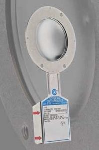
RUPTURE DISKS
These are non-reclosing devices for protecting against excessive pressure (or sometimes vacuum). A single or multiple rupture disks may be used in an instal lation. They also can serve as redundant pressure relief devices.
With no moving parts, rupture disks are simple and reliable – and faster acting than other pressure relief devices. Rupture disks react quickly enough to relieve some types of pressure spikes. Because of their light weight, rupture disks can be made from high-alloy and other corrosion-resistant materials that aren ‘t practical for relief valves.
A rupture disk is also a temperature-sensitive device. Burst pressures can vary significantly with its temperature, which may differ from the normal fluid operating temperature . As the temperature at the disk increases, the burst pressure usually decreases. Because the effect of temperature depends upon the rupture disk design and material, consult the manufacturer for specific applications. Specify the pressure and temperature at which the disk is expected to burst.
SIZING AND RELIEF PRESSURE
Carefully evaluate the contingencies that can cause overpressure in terms of the pressures generated and the rates at which fluids must be relieved. You need the package’s process and instrumentation drawings, equipment specification sheets, and design basis for the facility to calculate the individual relieving rates for each pressure relief device. An important parameter is the set pressure of a PRV installed in the machinery, package or facility. As a rough guide, this set pressure could be 110% of the maximum allowable working pressure (MAWP) in the package or system protected by a single pressure relief device sized for operating (non-fire) contingencies .
A multiple-device installation requires the combined capacity of two or more pressure relief devices to alleviate a given overpressure contingency. In this way, you might increase the set pressure, for instance , to 118% of the MAWP in a package protected by multiple pressure relief devices sized for operating (non-fire) contingencies . For fire cases, the relief pressure (set pressure) usually is higher – e.g., it could be around 120% or 125% of the MAWP in a package protected by devices sized for fire contingencies.
OVERPRESSURE CAUSES
An unbalance or disruption of the normal flows of fluid and energy in a machinery system or package can prompt the energy or fluid, or both, to build up in some part of the package (such as its discharge). Analysis of the causes and magnitudes of this over pressure, therefore, is a special and complex study of energy and fluid balances in different machinery operating scenarios.
Double-jeopardy scenarios usually aren’t credible ones for sizing a PRV. Such scenarios generally involve two independent failures or malfunctions at the same time – e.g., simultaneous failures of two completely independent machines or controls, or operator error leading to a blocked outlet coincident with an overall plant power failure. On the other hand, treat instrument-air failure during fire exposure as a single jeopardy if the fire exposure causes local air line failures.
Excessive speed and other machinery malfunctions can result in overpressure. Sometimes, the inadvertent opening of a valve from a source of higher pressure, such as a high-pressure process fluid, can lead to overpressure. For instance, in many packages the re’s always a possibility of the suction system becoming pressurized by the discharge (high-pressure) fluid; in many cases, some portion of the suction system actually is designed based on discharge pressure or other means of protection (such as a PRV is considered.
A single check valve isn’t always an effective means for preventing overpressure by reverse flow from a high-pressure source such as a high-pressure discharge. For example, if a fluid is pumped or compressed into a system that contains fluid at significantly higher pres sure th an the design rating of the equipment upstream (suction) of the pump or compressor, loss of pumped flow with leakage or latent failure of a check valve in the discharge line results in a reversal of the fluid’s flow. When high-pressure fluid enters the low-pres sure system, overpressure can result . In most cases, you should focus on prevention of reverse flow. It’s important to note that , in addition to overpressure of the upstream system (or suction system), reverse flow through machinery might destroy mechanical equip ment, causing loss of containment. In many cases, this hazard is of concern , so provide additional means of backflow prevention.
Even proper inspection and maintenance might not completely eliminate check-valve seat leakage and leakage will occur. Consequently, even without total failure of the check valve, the low-pressure system upstream of a check valve still could be over-pressurized. A detailed analysis and study on a case-by-case basis then can show whether automatic isolation, a pressure-relief device sized for leakage, or an alternative means of protection is needed. You must define the appropriate leakage rate for each
specific machinery system. Experience has shown that when inspected and maintained to ensure reliability and capability to limit reverse flow, two back-flow prevention devices in series suffice to eliminate significant reverse flow.
In addition, carefully evaluate the possibility of overpressure developing from the loss of any utility service (such as cooling water, electricity, etc.), whether plant-wide or local.
AMIN ALMASI is a rotating equipment consultant based in Sydney, Australia. This post originally appeared in Chemical Processing Special Report: Review Your Rupture Disc Regimen found here.